
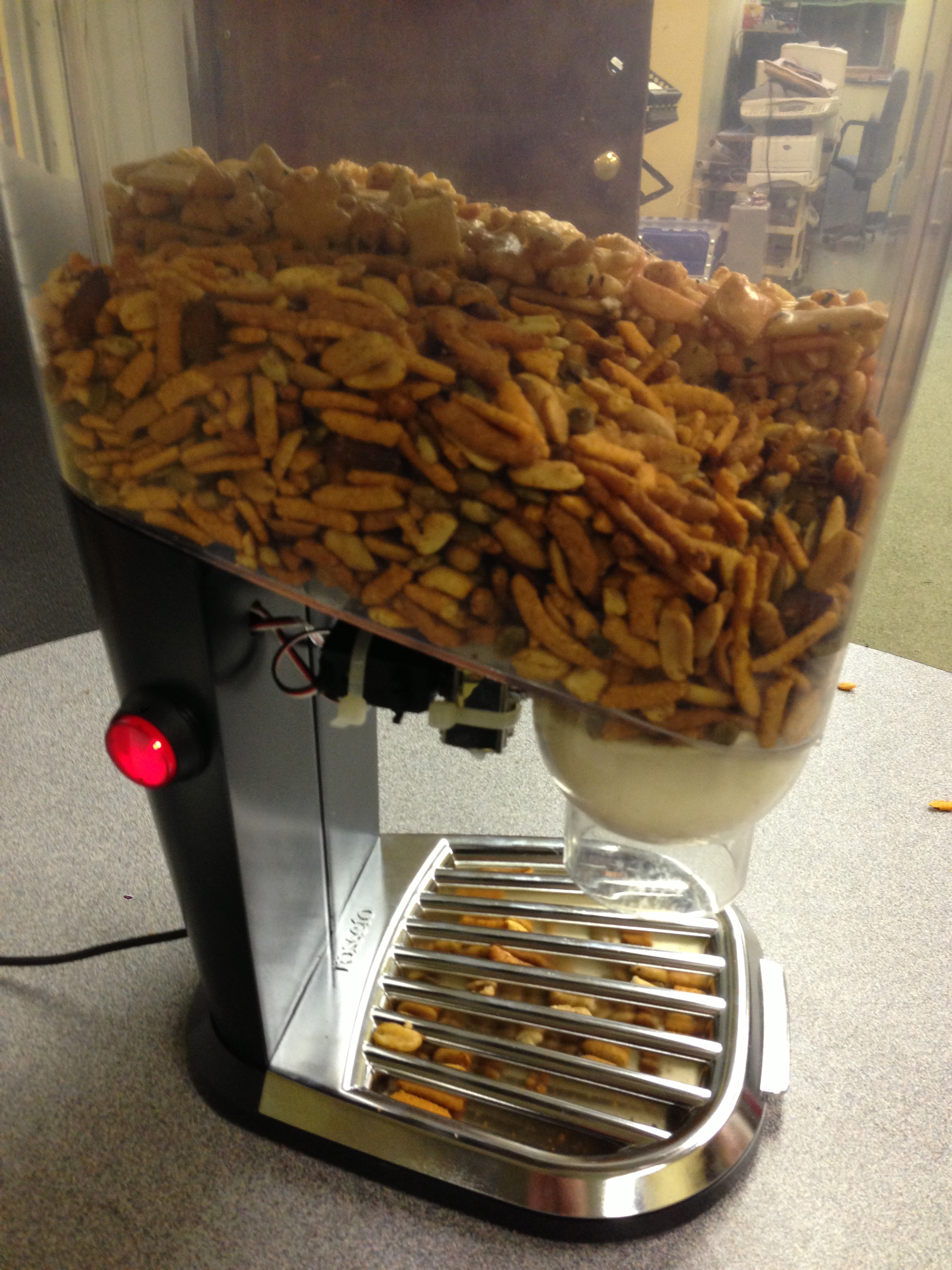
Back in February 2013 I started teaching my Raspberry Pi 101 class. After the first class I think I had Pi on the brain, I was scheduled for a quick weekend trip out of town with my girlfriend, and she was due to leave her two cats behind. She said that she was going to leave a large bowl of cat food out, and with that I suggested that I build an automated cat feeder for them.
Ya know, so the cats don’t over eat, and maybe have a mixture of food, and it’s super cool! (Did I mention that it’s cool!?) So… five days before leaving town, I purchased the food hopper, and very quickly ran out of time to complete the project before leaving on vacation. So plan B it was, a large bowl of cat food, and water.
However, I did stick with my original plan, and saw the build to completion well before my next trip out of town. In this blog post, I’ll list out the step-by-step (for the most part) process to building your very own Wifi Enabled Raspberry Pi Powered Cat/Human Feeder.
I’ve published a Google spreadsheet here, that lists the specific parts and components that you need to acquire for this project. It’s really simple, and can be easily assymbled in about 4-6 hours once you have all the parts.
Tools required:
- Soldering Iron
- Drill
- 1/2″ drill bit
- 1″ drill bit (for push button switch, optional)
- Hot glue gun + glue
- Wire cutter
- Pliers
Prerequisites for the build:
- Have all the parts on-hand, check out the spread sheet.
- Have a working and installed OS on the Pi. Adafruit Occidentalis or Raspbian work well.
- Have the Wifi Adaptor setup and ready to go: Occidentalis or Raspbian
- Play around with the GPIO in and out on the Pi by downloading the code from my GitHub Repo
- Install the Python GPIO.PWM module: RPIO install docs
Mount the servos!
The continuous rotation servos need to be attached to the handles to rotate the flapper wheel. First thing first, test to see if the servo is powerful enough to move the flapper handle. I grabbed some gaffer tape in this case, and taped it to the front of the handle, and held on to it, while telling the servo to run.
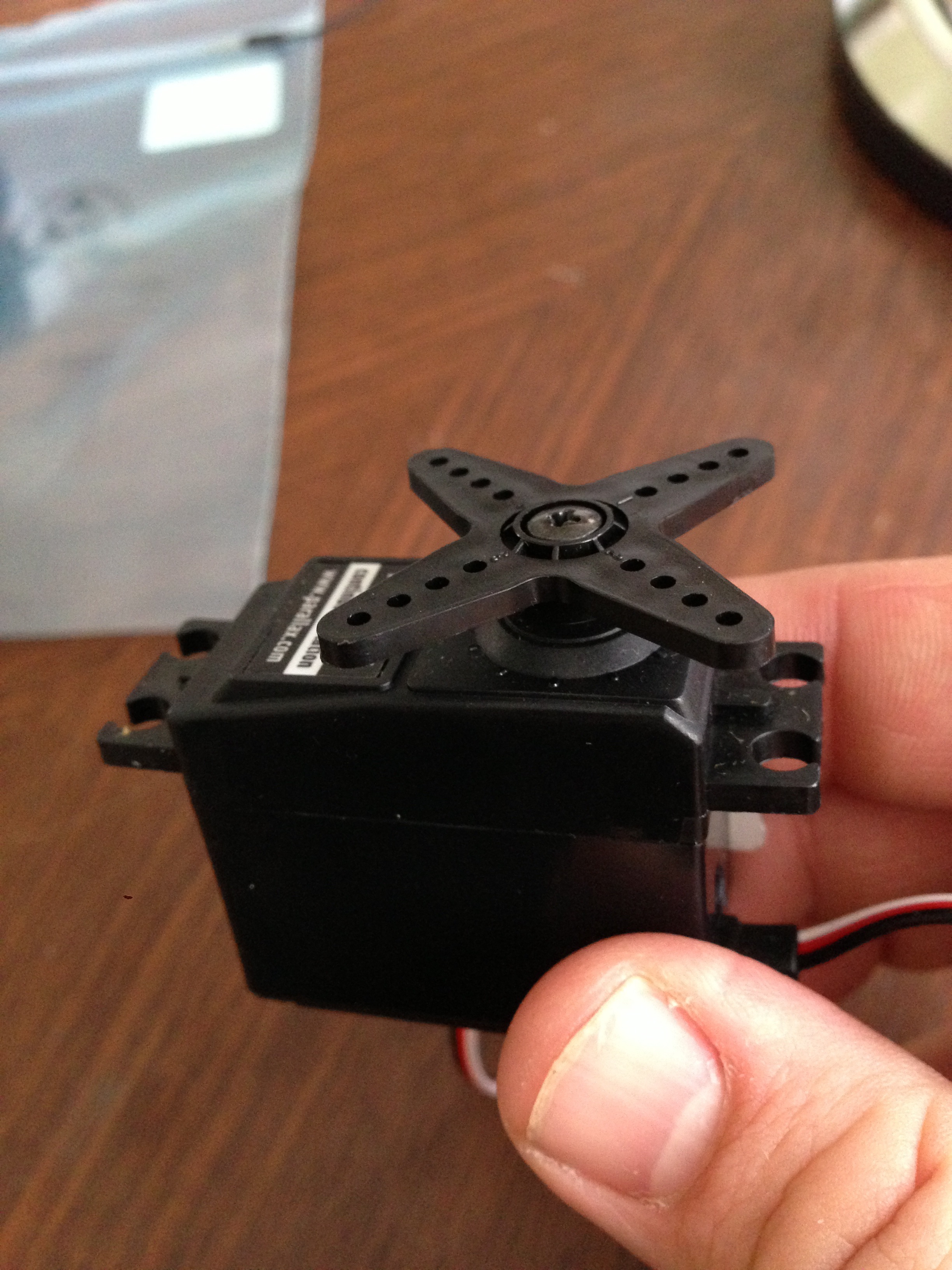
This at least told me that the servo could move the flapper around without to much of an issue. Granted there isn’t a load on this, as we don’t have any food stuff in it.
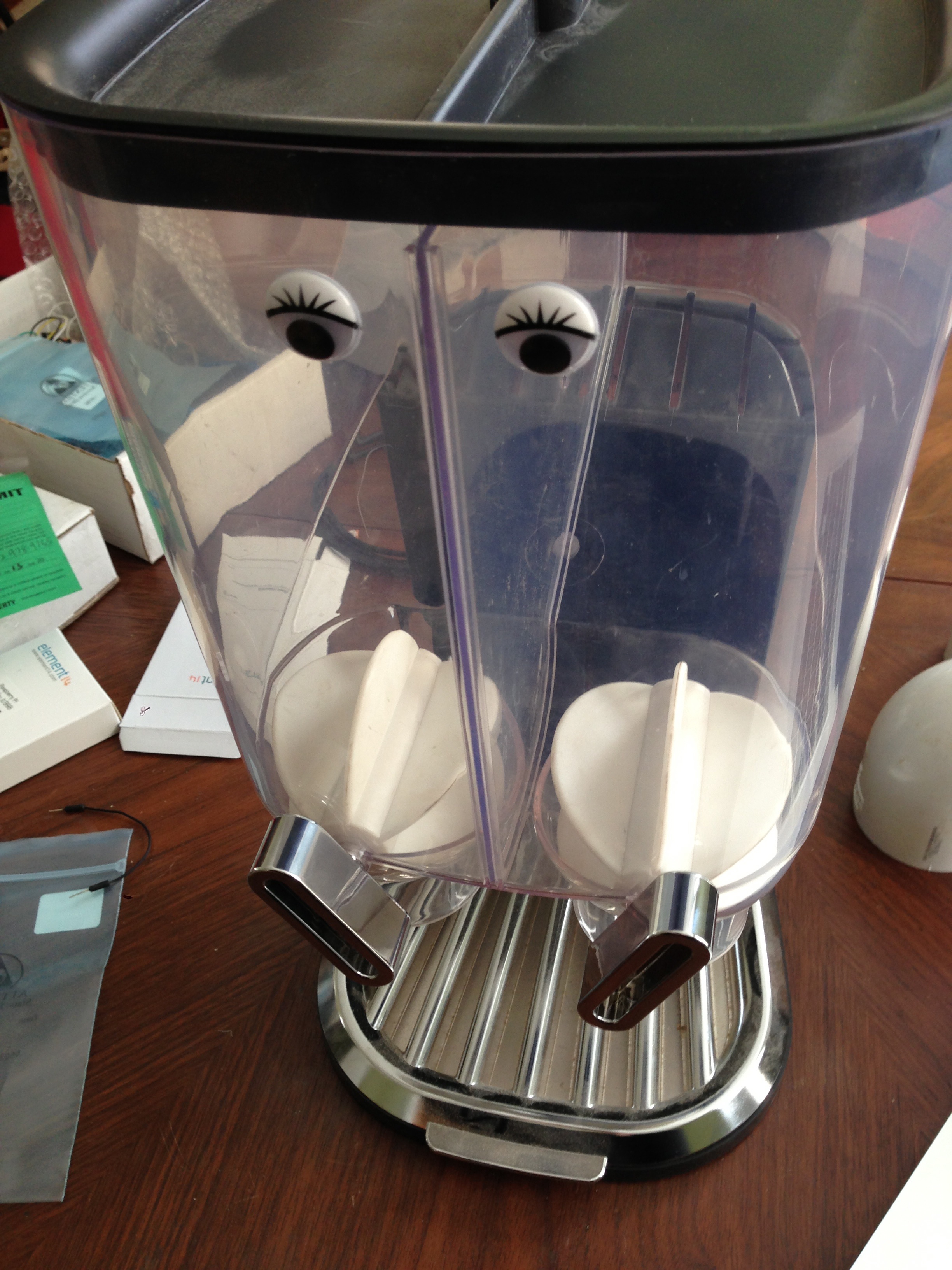
Next I decided that the handles should be on the back side, so that they are not exposed to someone hitting or bumping them (or getting caught). So I moved the handles to the back side. By moving the handles to the back, I needed to remove about 3/4″ on each end. This way the handle could easily rotate in a 360deg circle.
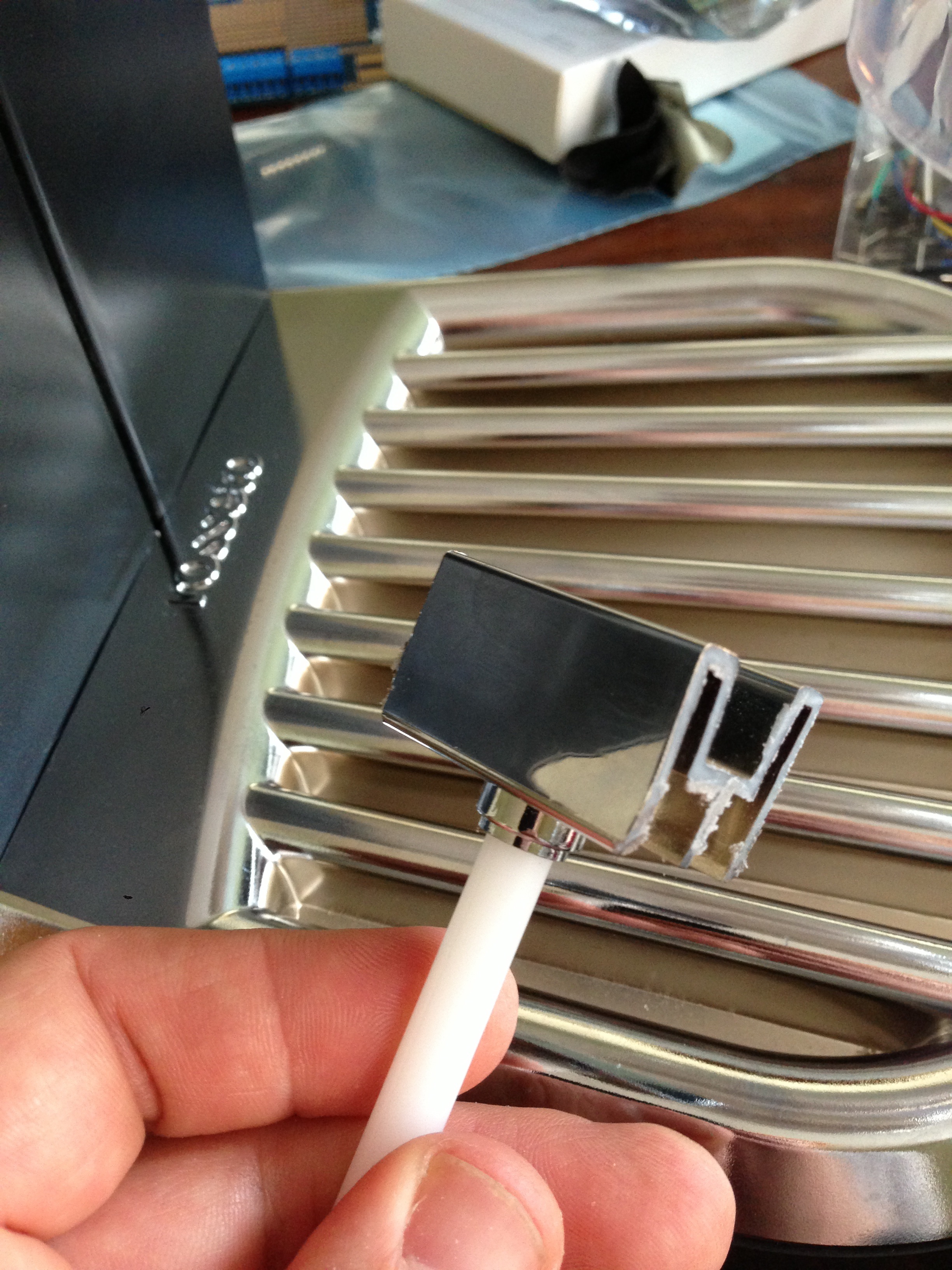
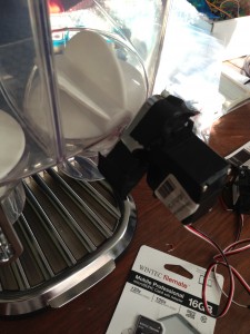
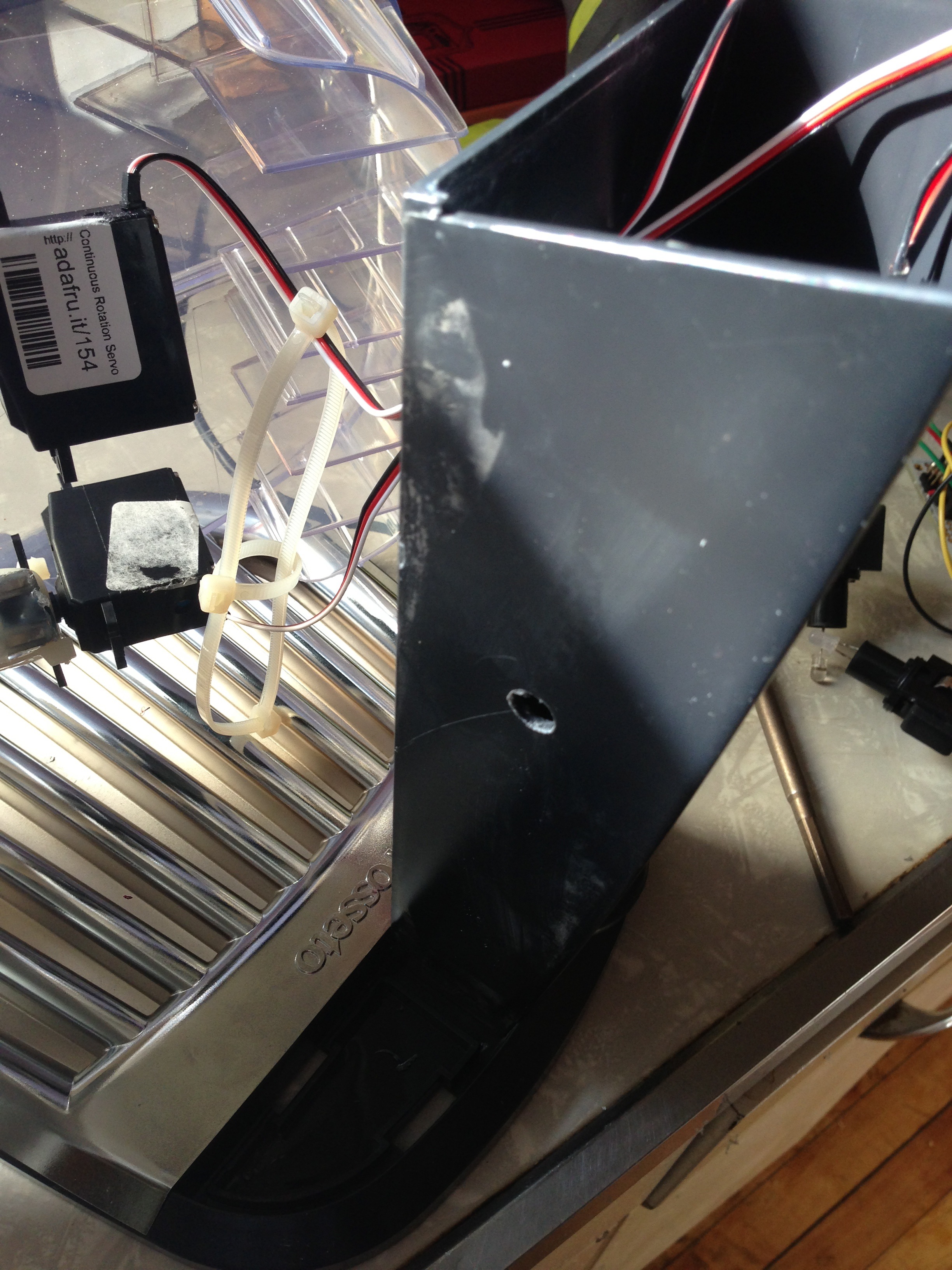
Now lets cut out a channel for the servo head…
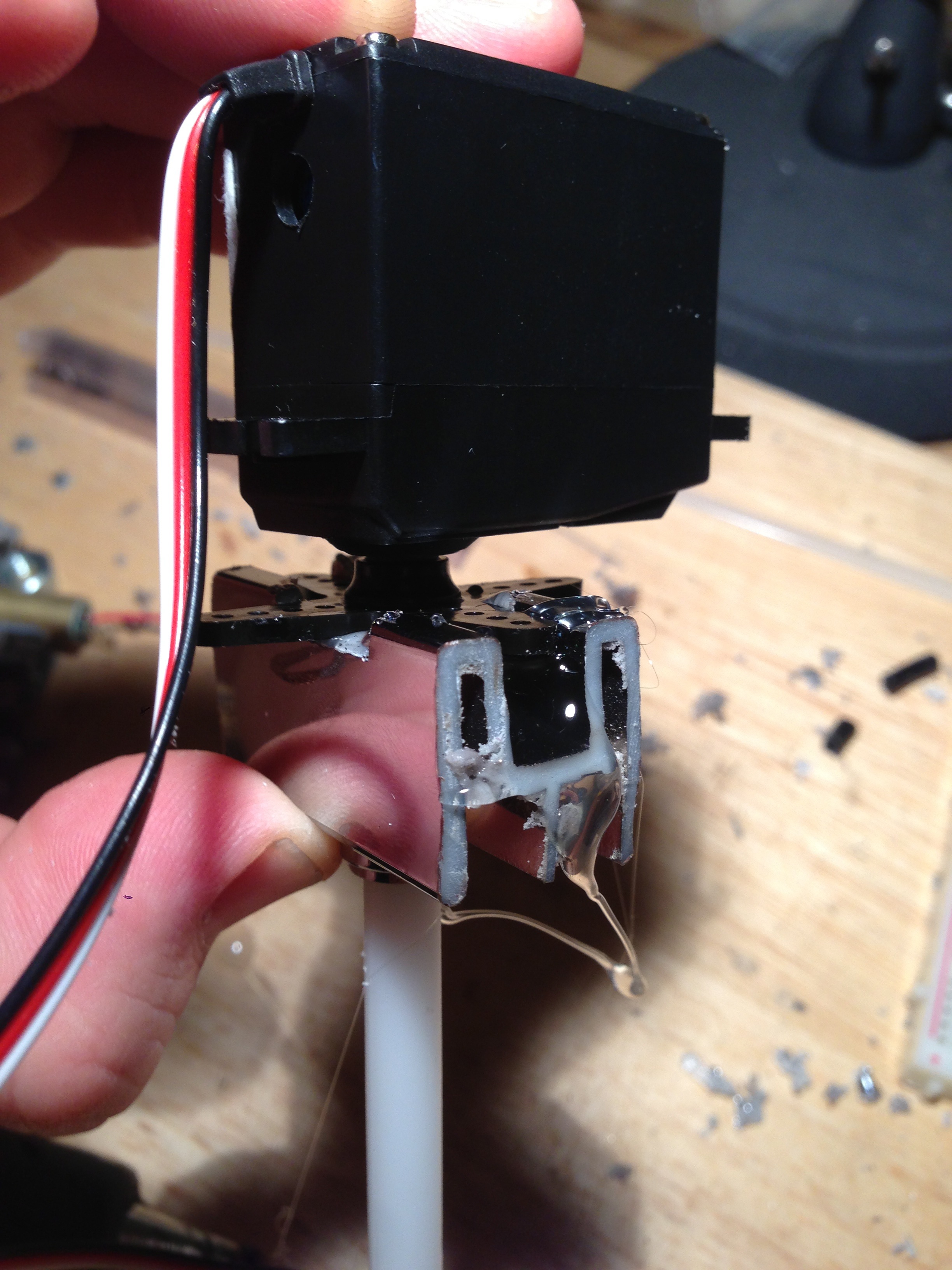
 I eventually ended up cutting out about 2mm into the channel, and basically making an outline for where the servo should sit. This was mostly so that when I stick this guy on with hot glue, it has something to push against, where as if it were placed on the surface, it would not have the leverage and it would break very quickly. Hot glue is great for holding things in place, but not for making strong mechanical joints. I also added two zip ties, and for support after the hot glue had started to set.
As you can see I’ve made a channel for the servo header, and attempted to make the servo shaft as close to center as possible. However it’s not 100% in the center, and that’s ok.
Wire it all up!
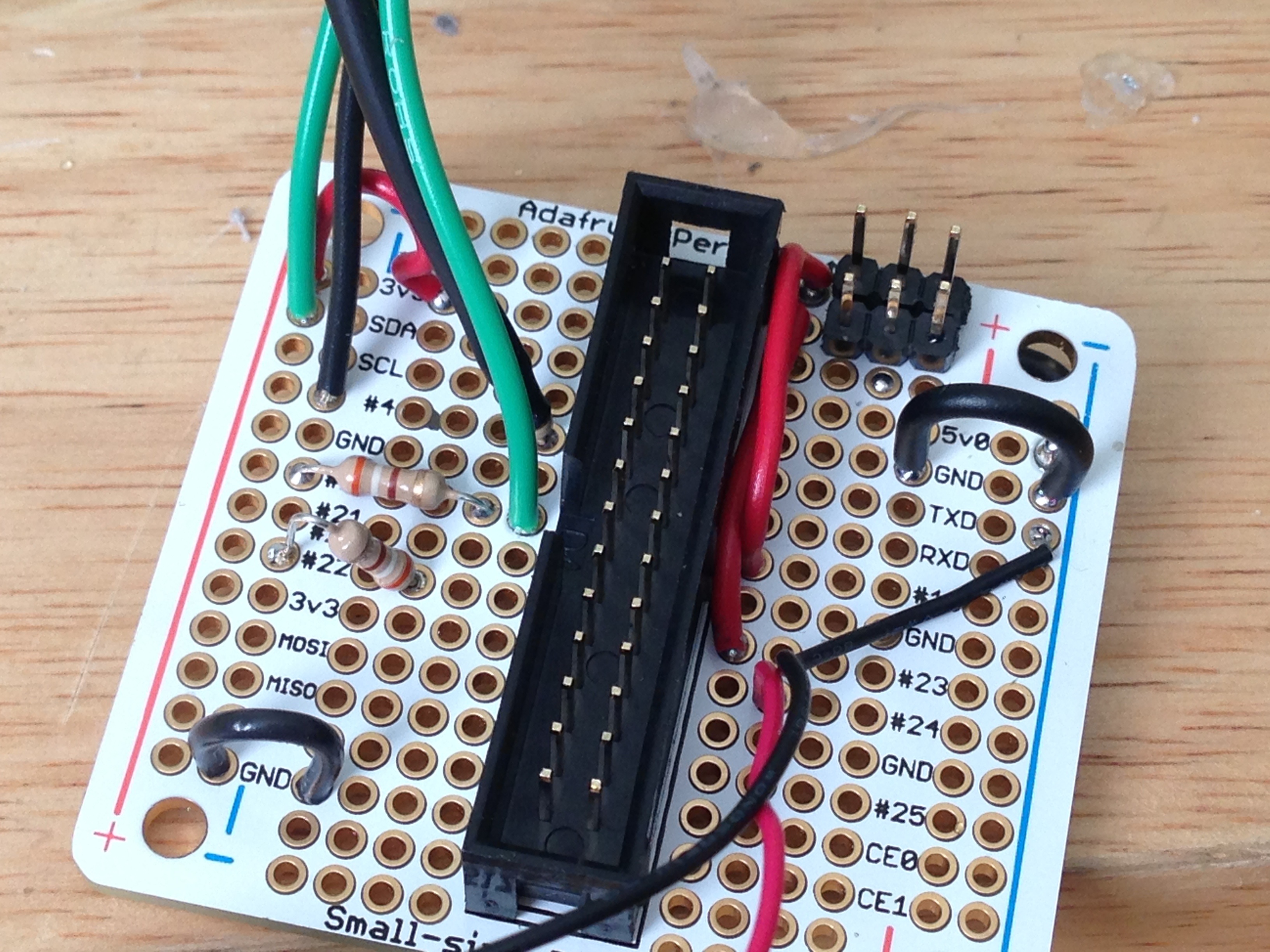
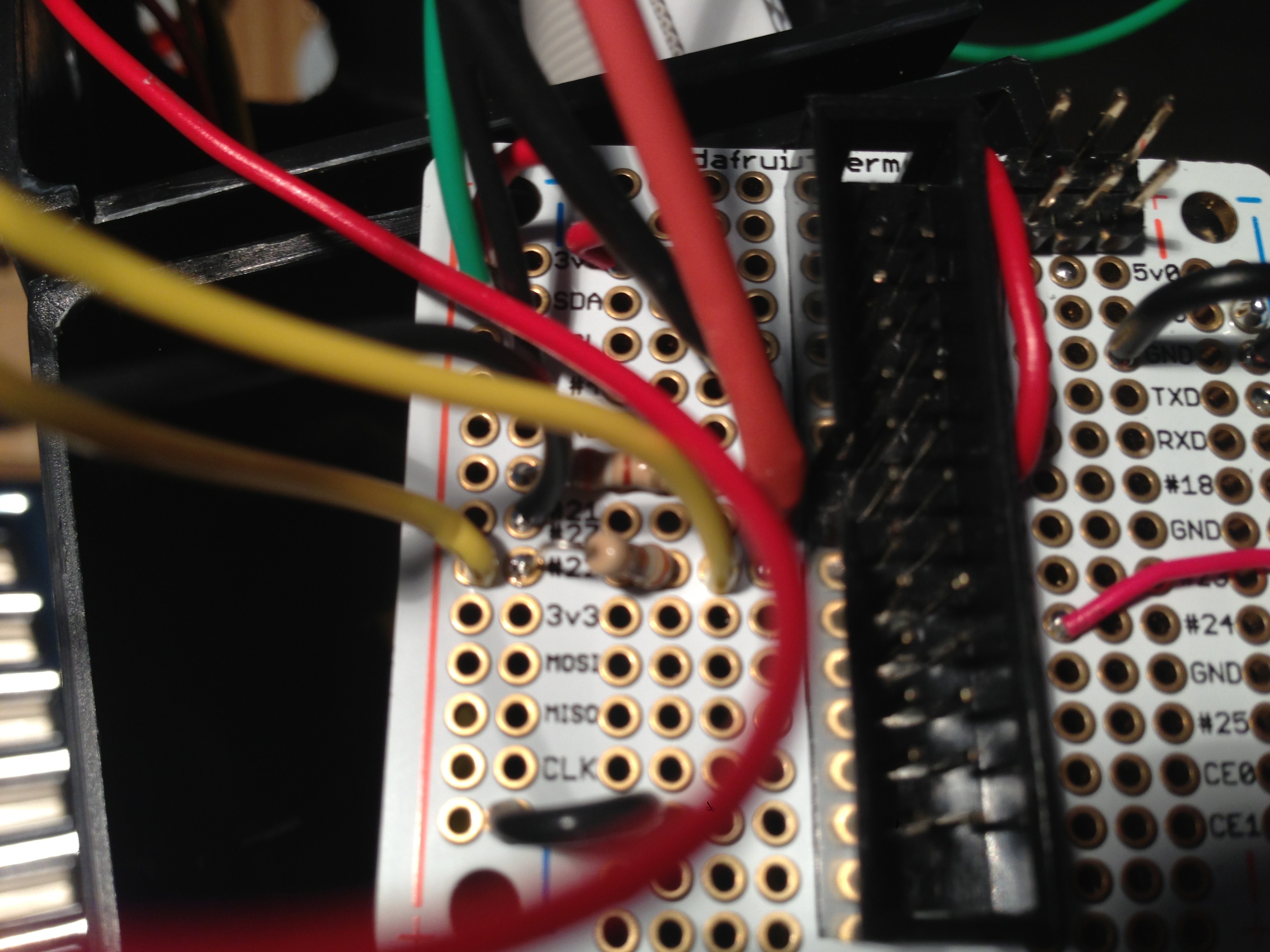
I used a “Small-Size Perma-Proto Raspberry Pi Breadboard PCB Kit” from Adafruit on this one. Start by adding a three pin header to the board for each servo. This makes it easy to plug/unplug the servos.
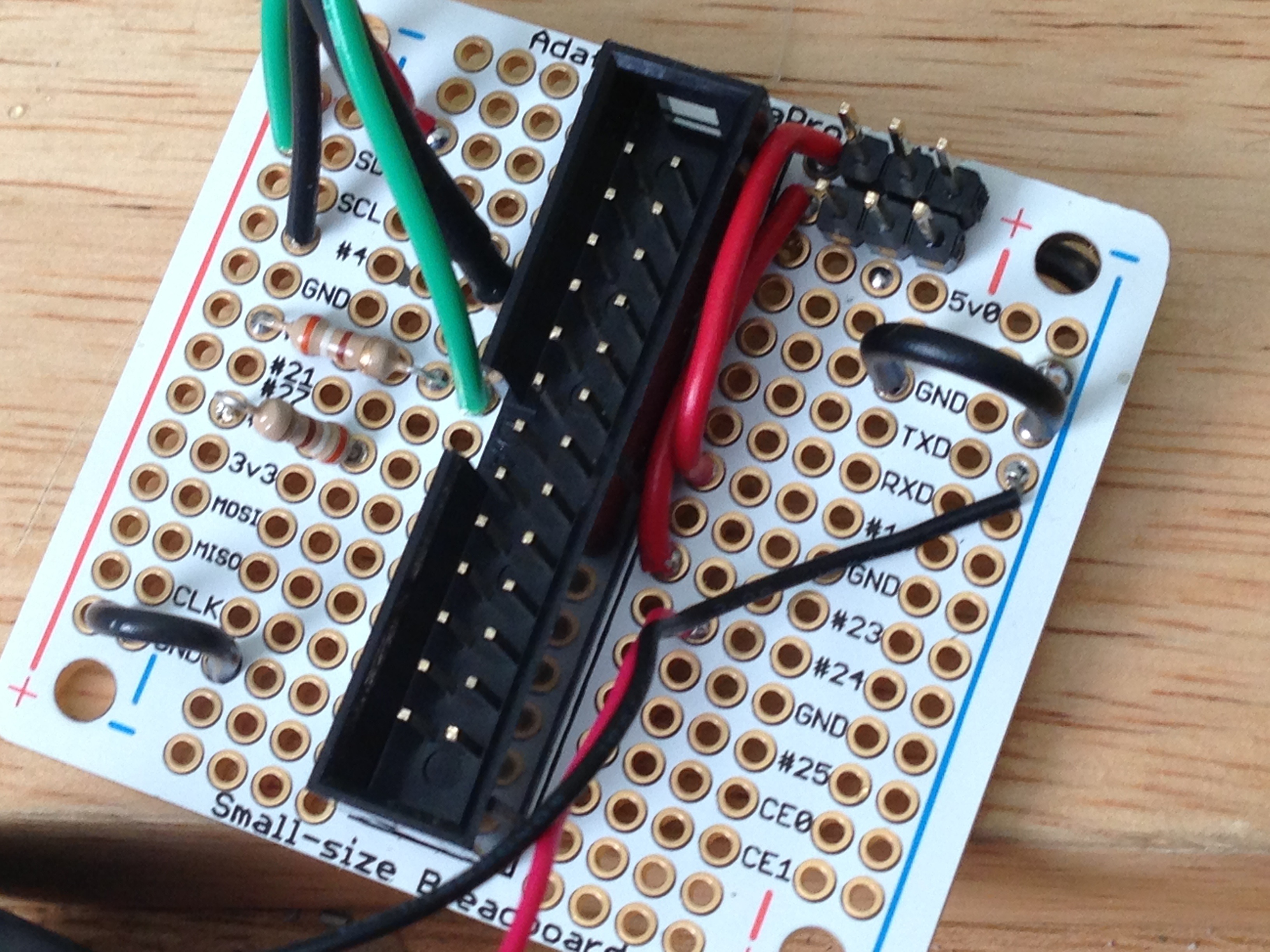
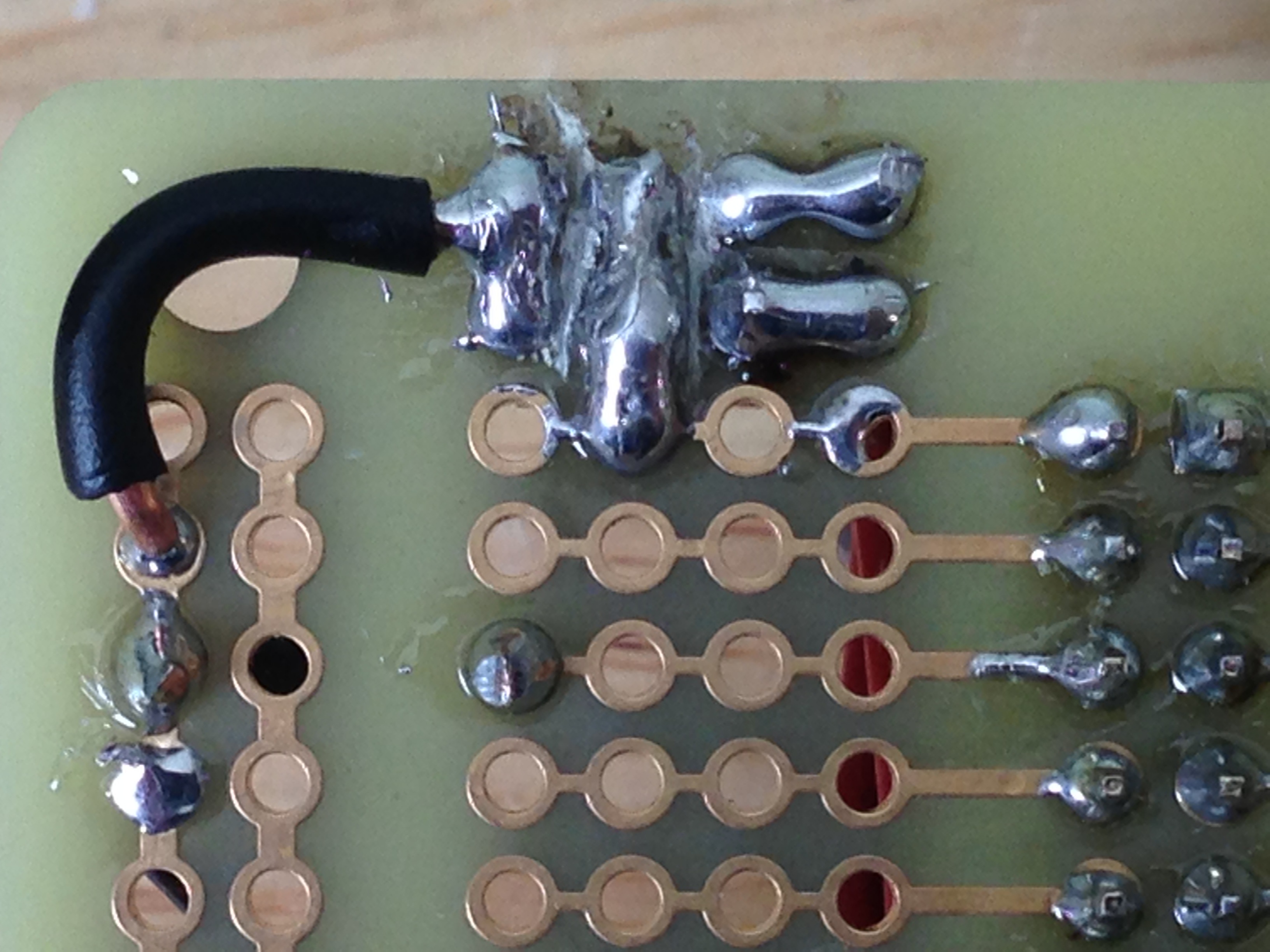
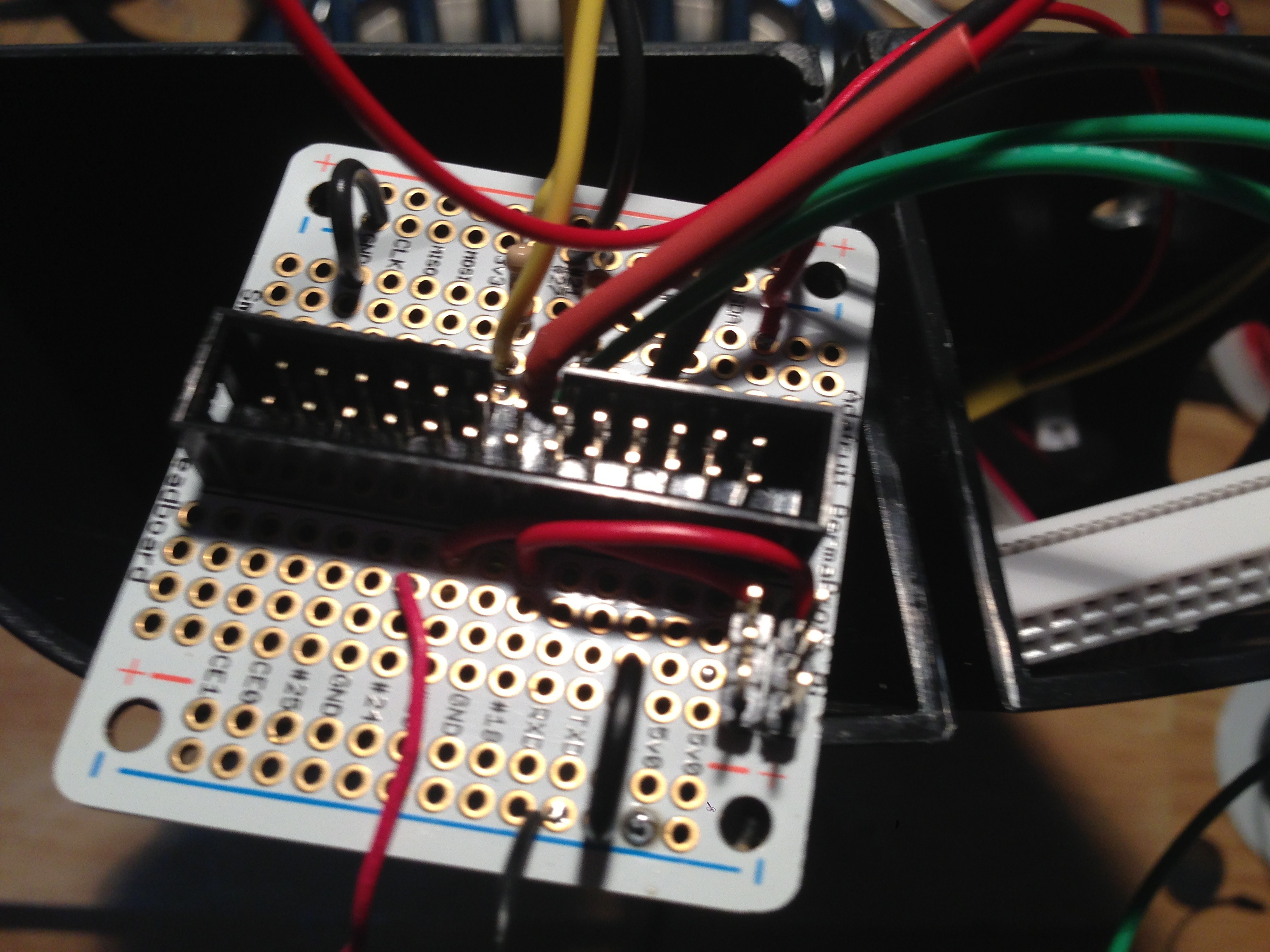
Back side of the board….

If you look a the back side, where I soldered the Servo headers, I made one of them a 5V solder bridge (from the 5V rail on up), The other one on the left is a ground solder bridge, and a link to the first hole, where I wired the GPIO outs from PINs 18 and 23.
To make this work, you first need to use a nippers (side cutters or a dyke) and carefully clip the traces on the top two rows. Once the traces are gone, you can then solder in the header connections for the servos.
Next, we need to add on in a current limiting resistor for the LED lights, as we don’t want to blow them up! A 390Ohm resistor soldered on to a wire works great!
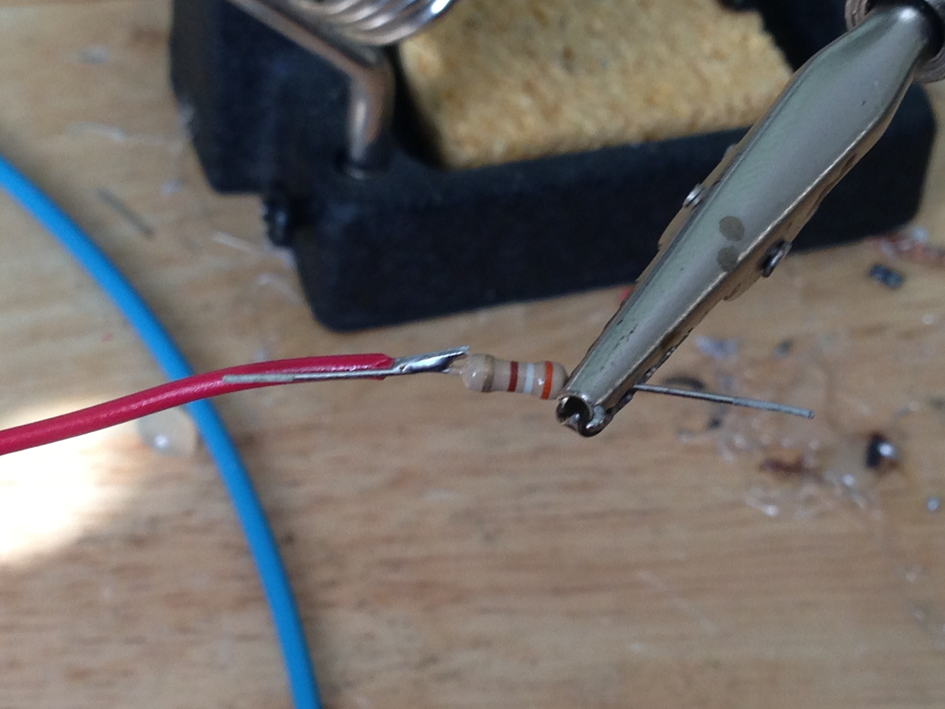
Make sure you add some heat shrink tube before you solder the resistor on…
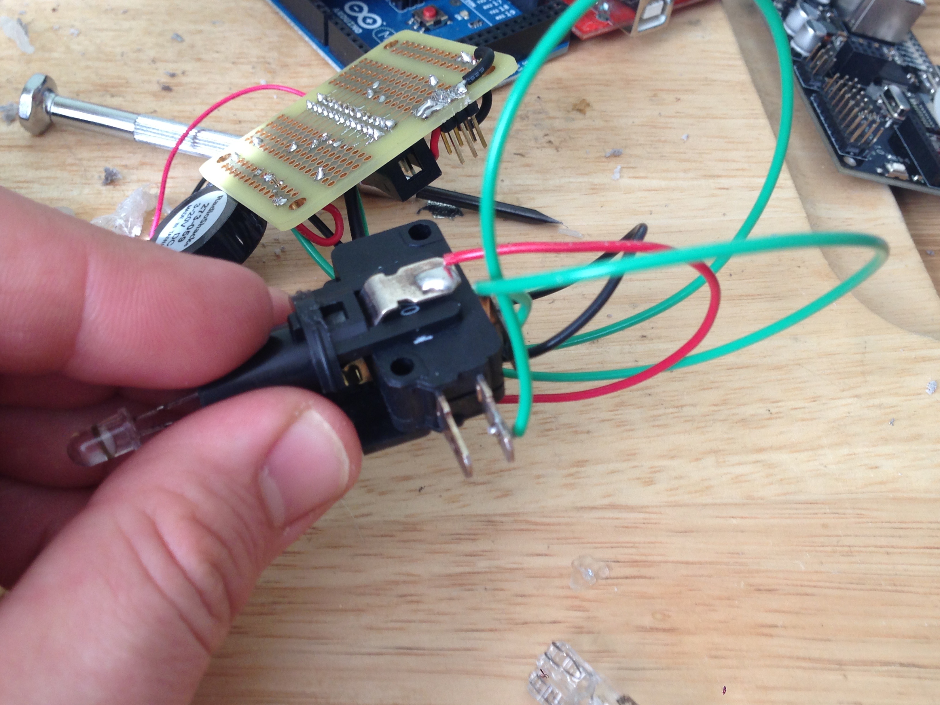
 I had a button with a 12v neon lamp in it, but wanted it to use an LED instead.
So, I replaced the bulb with and LED, just open the switch (easier said then done), and swapped out the bulb for an LED and added a little bit of solder. Connect the resistor side of the two LEDs to pins #4 and #27 on the breakout board for the output. Connect the negative side to the negative rail (don’t forget to connect the negative rail to the GND row).
 Now, we want to have a button that does something when a human pushes it. In this case, we are using that same 390ohm resistor as what is called a “pull down” resistor. The resistor is connected to ground, and ensures that our input pin doesn’t “float” in a state of sudo high, but not really high. Then we hook the other side of the switch up to the 3v rail. When the switch is pushed it reads as “High” in the GPIO system or “True” in python.
Lastly hookup your beeper to pin 24, and ground.
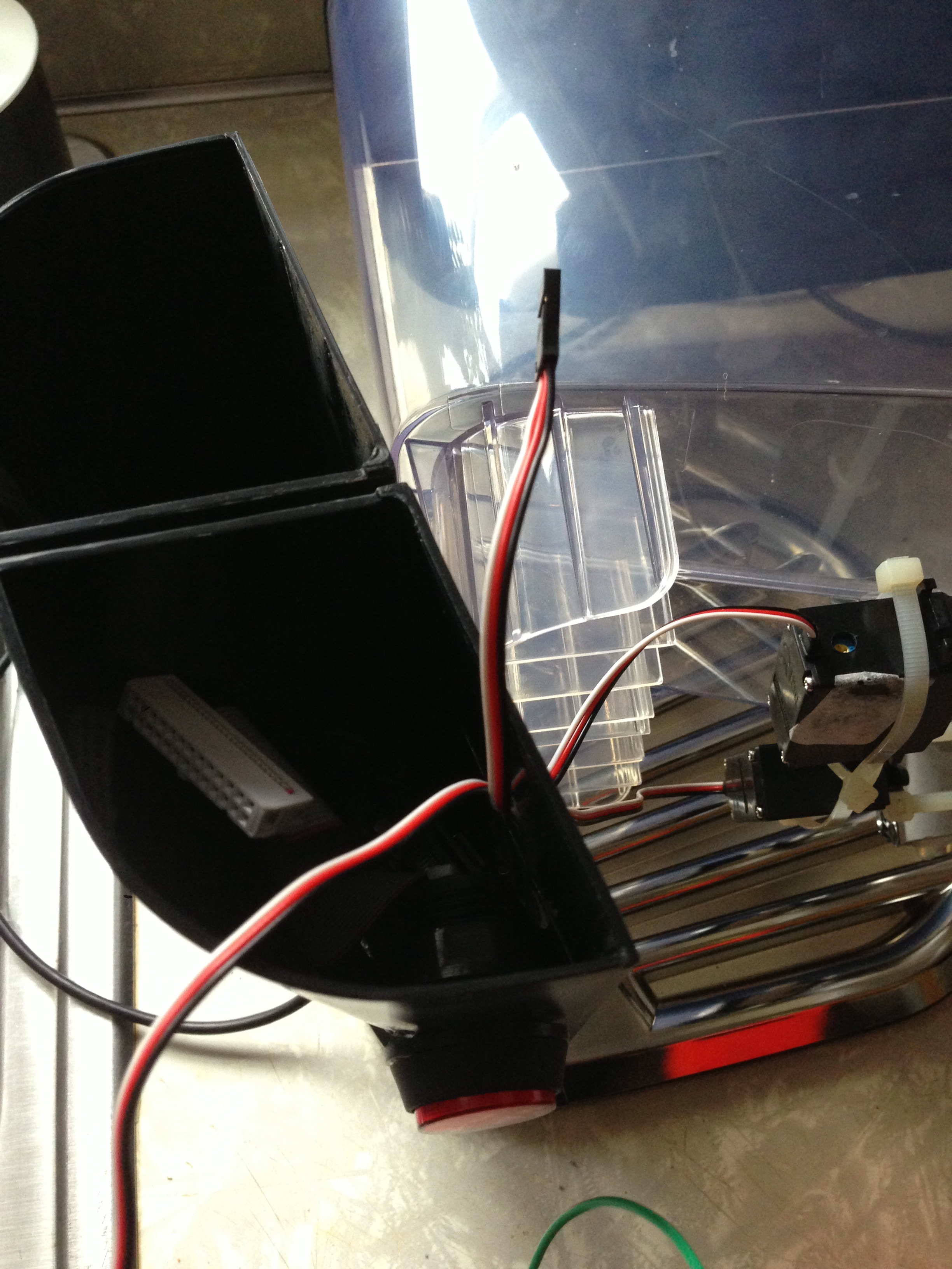
Now, once everything is soldered, and you have tested it all by pushing buttons and such, now you can begin to modify your feeder case, and stick it all back together… I drilled holes for the USB power cable, the servo headers, a through hole, and the side buttons.
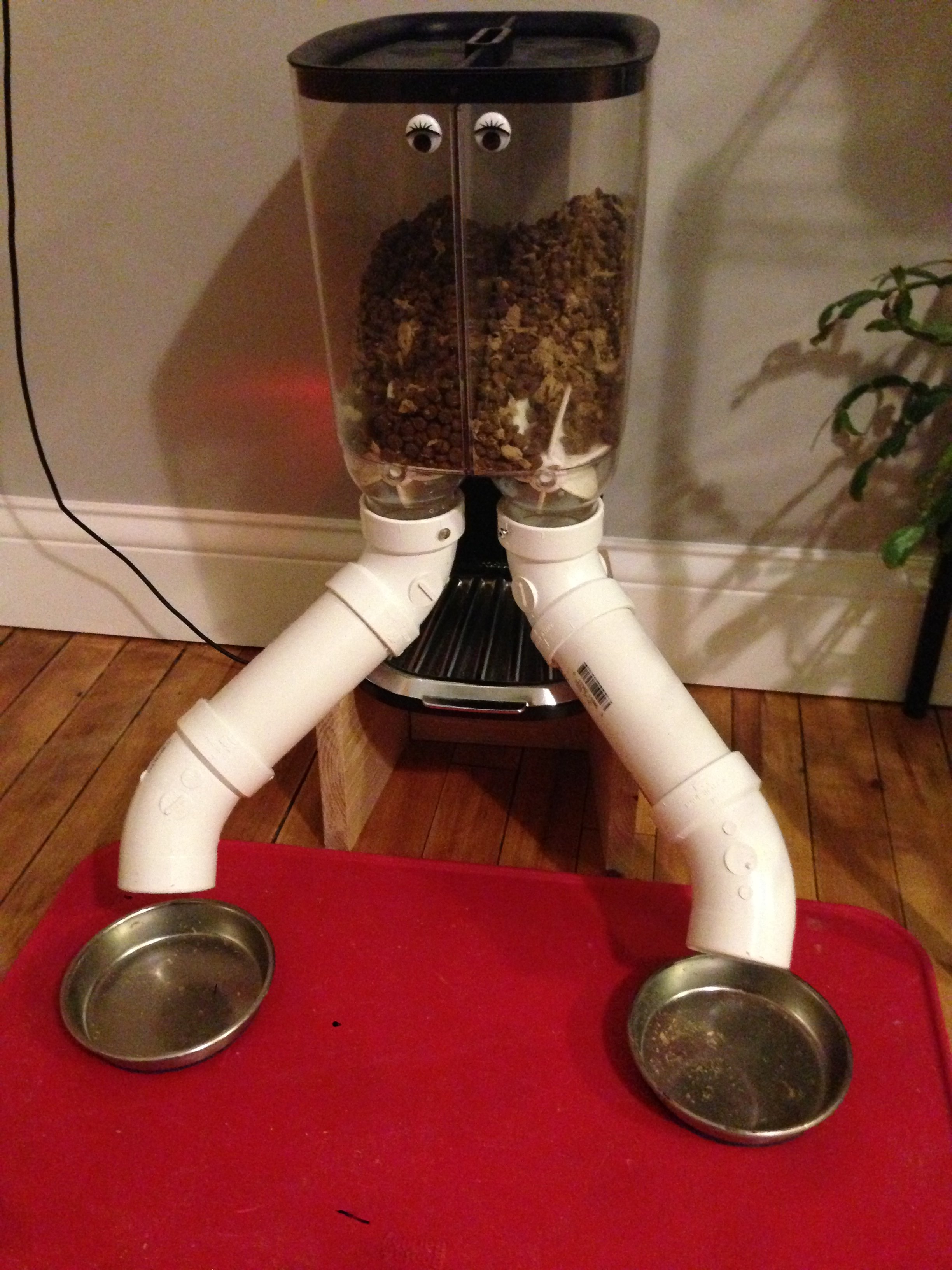
And then I jammed it all into the one pillar…
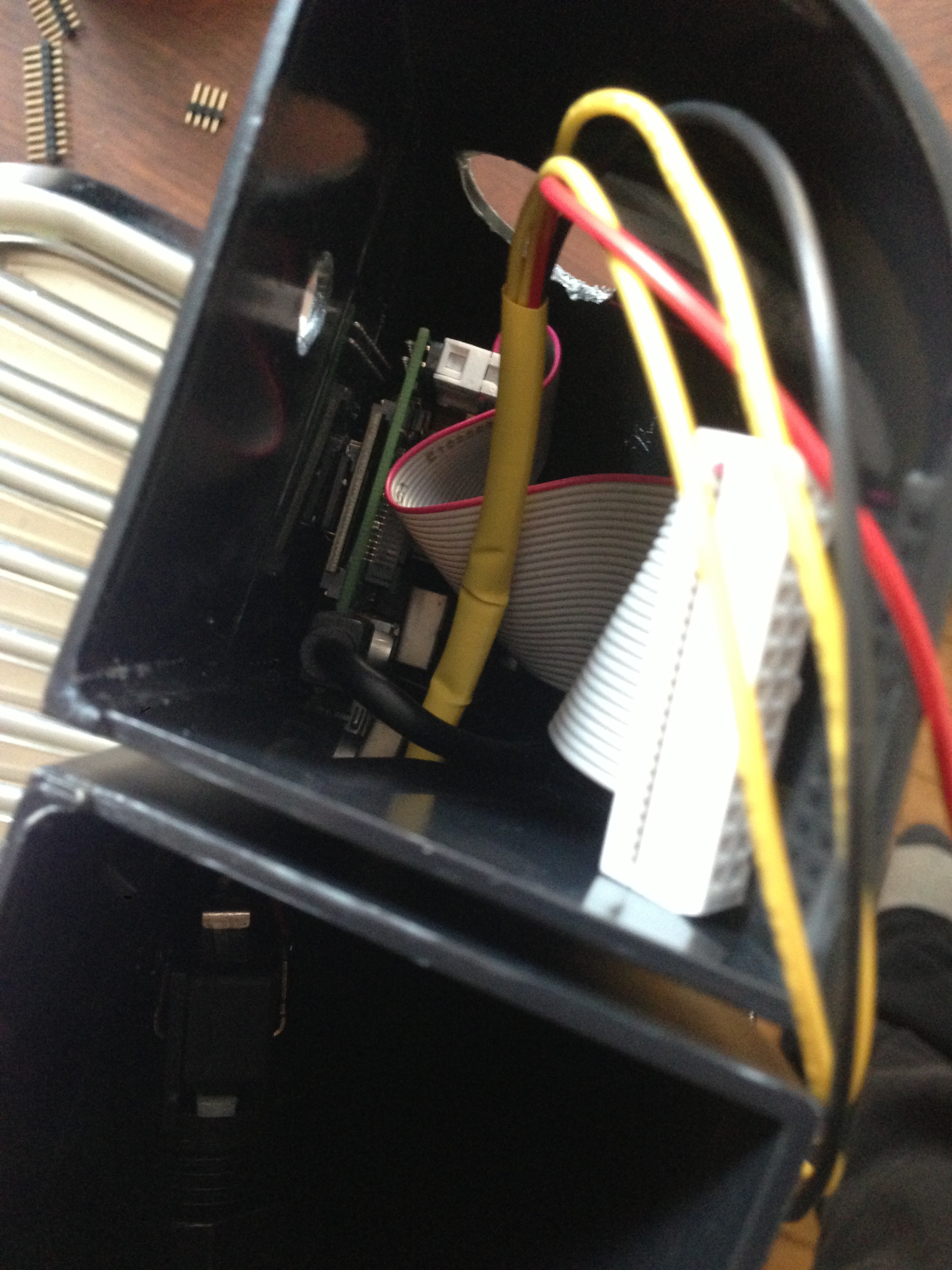
Now it looks like this:
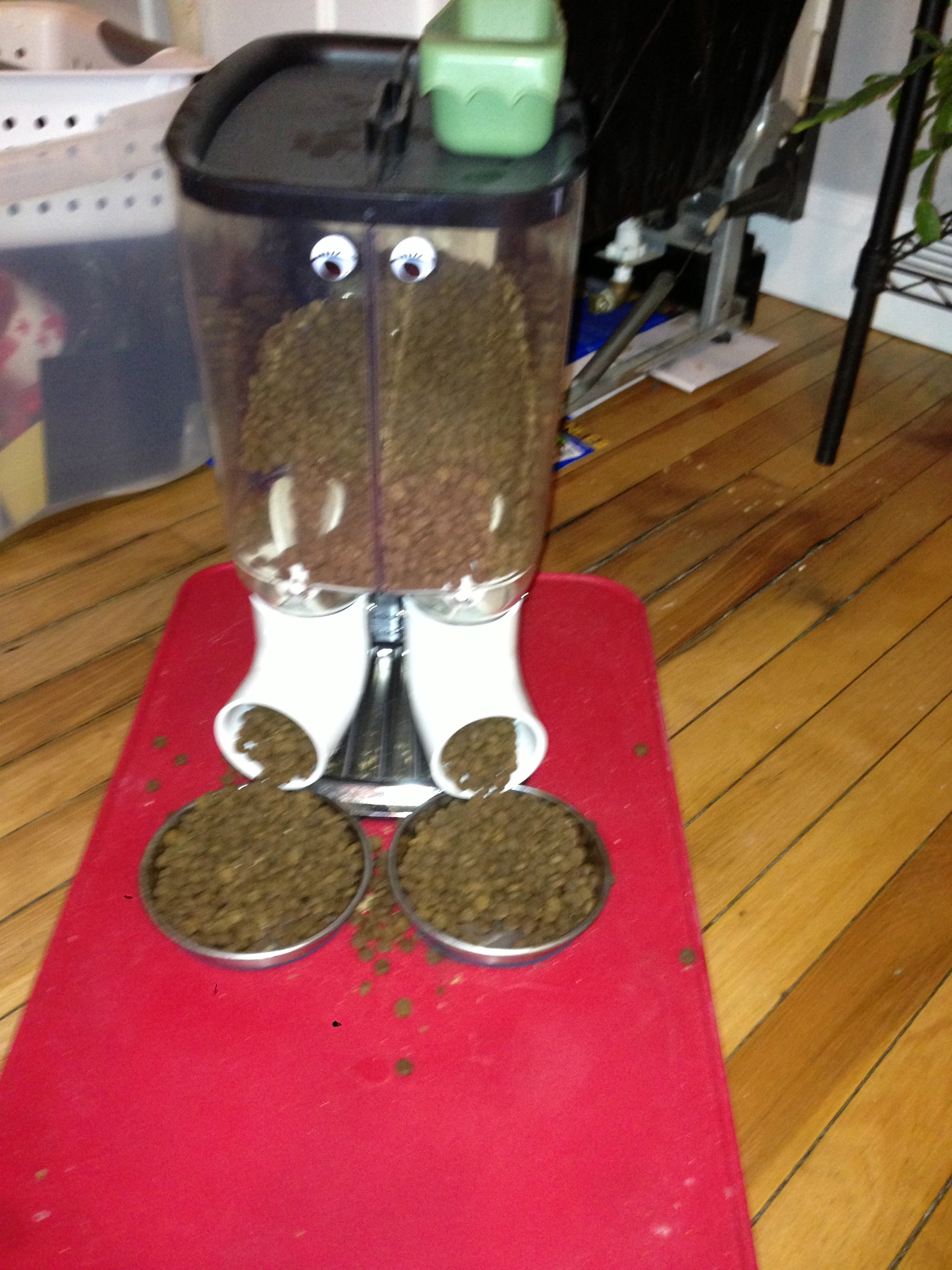
Now, set it up and test it!
Future improvements include:
- Pi camera
- Mobile WebUI using PiUi
- Powered speakers
- Audio clips from red dwarf, specifically the Cat requesting fish.
Contact info:
Twitter: @_videoman_
Email: dave at nospam drstrangelove dot net
4 thoughts on “Raspberry Pi Power Cat Feeder – Updates”
Comments are closed.